
Multi-objective Design of an Unmanned Underwater Vehicle Propulsion Drive
This article takes excerpts from the publication Multi-objective Design of an Unmanned Underwater Vehicle Propulsion Drive authored by Drummond R. Fudge, Steven D. Pekarek, and Scott D. Sudhoff.
To enable design, first an integrated multi-objective design optimization of the inverter/motor and propeller is undertaken. The resulting Pareto-optimal front yields the trade-off between system loss (propulsion drive + hydrodynamic) and propulsion system mass. Next, a system optimization is carried out. In the system level optimization, the Pareto-optimal front of the propulsion system is combined with a battery model in order to find the trade-off between propulsion system mass and vehicle range, which could equivalently be viewed as available payload mass versus range.
Battery Model
The complete system level design of the UUV power and propulsion system includes battery pack selection. To ultimately generate complete power and propulsion system designs, a battery pack model is needed to relate battery pack mass, propulsion and hotel power demand, and minimum voltage to the battery pack discharge duration. To this end, a lithium-type battery pack modeling technique has been developed that allows for accurate prediction of battery discharge duration and quick parameterization of different battery makes/models (MMs) to fill out the design space.

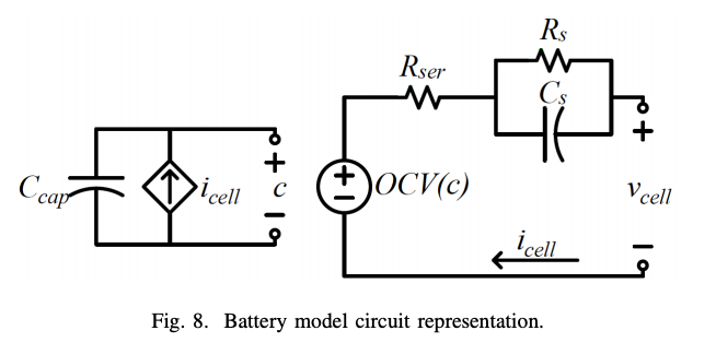
The modeling technique relies on the circuit-based battery model architecture in [7] with certain changes that improve ease-of-use and utility for multi-objective system-level design. The first major change compared to [7] is a reduction in model complexity in order to enhance the simulation speed within multi-objective optimization. In exchange, this change yields degraded transient accuracy, but does not suffer accuracy in predicting model discharge duration. Fortunately, transient accuracy is not a necessary consideration as the power demand is assumed constant throughout the entire discharge cycle. The model presented herein does not consider any effects on battery performance outside of the state of charge. The circuit representation of the battery model is shown in Fig. 8 for a single battery cell. A notable difference between this modeling technique and existing models is the use of state of discharge.
Adaption for Power and Propulsion System Design
The system level design requires an electrical and mass description of the entire battery pack, which is composed of many cells. The electrical parameters of a battery pack can be scaled up from a single cell by specifying the cell MM, the number of cells in series, and the number of strings (sets of series cells) in parallel. The mass of the battery pack is readily determined by scaling the specific energy (Watt-hours per kilogram) of the given cell by the total number of cells. Here, the specific energy term is adjusted to include the mass of the container(s) that hold the cells.
For a desired battery pack mass, power demand, and minimum voltage, a suitable battery pack can be specified to determine mass and simulated to determine discharge duration and minimum voltage. Start defining the suitable battery pack by selecting a parameterized battery cell MM.
Integrated Propulsion/Battery Design
The objectives for battery integration are to minimize total mass (electric machine + battery) and to maximize range. The motivation to minimize mass is that since the UUV has a fixed volume, the UUV mass must be necessarily fixed in order maintain neutral buoyancy. Thus the maximum payload mass is equal to UUV mass less the machine/battery mass. If the payload mass is less than the maximum, then ballast may be used to achieve neutral buoyancy. The desire to maximize range is self-evident.
The approach taken here to calculate the trade-off between range and mass is to assign two degrees of freedom. The first degree of freedom is the desired mass of the propulsion system, M∗ PD.
For the design space, the desired propulsion system mass is allowed to vary over the domain of the Pareto-optimal front; the desired battery mass is allowed to vary between 10 and 150 kg in this notional example. A single battery cell MM is considered for this example.
The second degree of freedom is the desired battery mass, M∗ B. From the desired battery mass and the desired dc voltage at end of the battery’s discharge, the number of cells and their arrangement can be deduced.
The resulting Pareto-optimal front is shown in Fig. 11. Therein, it is important to keep in mind that mass is being minimized while the range is being maximized. Not surprisingly, the total mass increases (and therefore maximum payload decreases) with range in an affine way. However, it is interesting to see that the battery and motor mass have a periodic component as range varies. This periodic component is driven by the fact that the number of cells is discrete and so battery mass is essentially discrete. Thus to interpolate between different battery levels, the propulsion motor design is being swept across its Pareto-optimal front. Although subtle, it can be seen that the motor (propulsion system) mass increases with range—indicating higher efficiency propulsion systems are being used at higher range.

Conclusion
The work proposes a multi-objective design paradigm for a UUV power and propulsion system that incorporates the propeller, permanent magnet AC machine, and battery pack concurrently. The design paradigm yields a Pareto-optimal front of designs optimized for mass and range. An example of a complete UUV power and propulsion system is demonstrated for the models discussed herein.